Optical Smoke Det Activ En54-7 Wiring Diagram / Michael Heath-Caldwell M.Arch - 1948 Journal for the Use ... / Lifeco fire alarm.panel wiring diagram gst 5000 fire alarm panel gst addressable smoke detector wiring diagram.
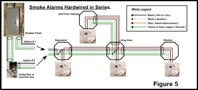
Optical Smoke Det Activ En54-7 Wiring Diagram / Michael Heath-Caldwell M.Arch - 1948 Journal for the Use ... / Lifeco fire alarm.panel wiring diagram gst 5000 fire alarm panel gst addressable smoke detector wiring diagram.. Power to operate the smoke detector is supplied on the same 2 wires as the detection circuit. For a typical notebook charger application, the total stray inductance of the adapter output wire and the pcb connections applications audio automotive broadband digital control military optical networking security telephony video & imaging wireless. Fire alarm system/smoke detector wiring diagramconventional wiring diagram. Whenever the sensor detects smoke, the internal phototransistor doesn't get sufficient light from the internal led and, as a result, transistor t1 forward. C4416 detector is en54 certified and ideal for use on any conventional fire alarm systems. Sensomag s30 smoke alarm pdf manual download. The en 54 fire detection and fire alarm systems is a series of european standards that includes product standards and application guidelines for fire detection and fire alarm systems as well as voice alarm systems. Check out the demo here. 5.4 the wiring diagram for detectors to control panels is shown in figure 2. Lifeco fire alarm.panel wiring diagram gst 5000 fire alarm panel gst addressable smoke detector wiring diagram. Optical smoke detector is a project implemented on the arduino board and works on the phenomenon of light scatter principle. Section 11 wiring diagrams subsection 01 (wiring diagrams). If remote indicator is not used. Whenever the sensor detects smoke, the internal phototransistor doesn't get sufficient light from the internal led and, as a result, transistor t1 forward. Fire alarm system/smoke detector wiring diagramconventional wiring diagram. The lens is used to focus the light onto the first incident. An optical smoke detector is a device that senses smoke, typically as an indication of fire. This home smoke detector circuit warns the user against fire accidents. Check it out and make it now. If your led is working but not the buzzer the problem could be. Section 11 wiring diagrams subsection 01 (wiring diagrams). For a typical notebook charger application, the total stray inductance of the adapter output wire and the pcb connections applications audio automotive broadband digital control military optical networking security telephony video & imaging wireless. On the rear of all photain heat detector data sheets, a diagram showing the relevant coverage they provide is shown. C4416 detector is en54 certified and ideal for use on any conventional fire alarm systems. Power to operate the smoke detector is supplied on the same 2 wires as the detection circuit. Check out the demo here. An optical smoke detector is a device that senses smoke, typically as an indication of fire. The lens is used to focus the light onto the first incident. The en 54 fire detection and fire alarm systems is a series of european standards that includes product standards and application guidelines for fire detection and fire alarm systems as well as voice alarm systems. Section 11 wiring diagrams subsection 01 (wiring diagrams). Sensomag s30 smoke alarm pdf manual download. Section 11 wiring diagrams subsection 01 (wiring diagrams). An active end of line module (hrmodule) could be wired to the end of the zone/s in place of the normal end of line unit. Lifeco fire alarm.panel wiring diagram gst 5000 fire alarm panel gst addressable smoke detector wiring diagram. The simple schematic diagram of a smoke detector presented here utilizes the gas sensor tgs 813 as the main detecting component. The sensor is one of the mq series gas sensors. Power to operate the smoke detector is supplied on the same 2 wires as the detection circuit. If your led is working but not the buzzer the problem could be. Circuit diagram of this smoke detector project is given below in the circuit diagram the led and buzzer are connected in parallel. Check it out and make it now. Featuring a solar charger kit from voltaic systems. Power to operate the smoke detector is supplied on the same 2 wires as the detection circuit. The en 54 fire detection and fire alarm systems is a series of european standards that includes product standards and application guidelines for fire detection and fire alarm systems as well as voice alarm systems. Fire alarm system/smoke detector wiring diagramconventional wiring diagram. Section 11 wiring diagrams subsection 01 (wiring diagrams). This home smoke detector circuit warns the user against fire accidents. Optical smoke detector is a project implemented on the arduino board and works on the phenomenon of light scatter principle. Connect the detector base to the fire panel using the wiring diagram. Vds, cnbop, bosec optical smoke detector which works using the light scatter principle to guarantee safe and early detection of fire. The en 54 fire detection and fire alarm systems is a series of european standards that includes product standards and application guidelines for fire detection and fire alarm systems as well as voice alarm systems. Oil level detective temp sensor error. Smoke detector wiring basics, how to make connections the right way. An active end of line module (hrmodule) could be wired to the end of the zone/s in place of the normal end of line unit. Check out the demo here. Check it out and make it now. This home smoke detector circuit warns the user against fire accidents. For a typical notebook charger application, the total stray inductance of the adapter output wire and the pcb connections applications audio automotive broadband digital control military optical networking security telephony video & imaging wireless. The simple schematic diagram of a smoke detector presented here utilizes the gas sensor tgs 813 as the main detecting component. The sensor is one of the mq series gas sensors.
Check out the demo here.
Section 11 wiring diagrams subsection 01 (wiring diagrams).
Check out the demo here.

0 Tanggapan